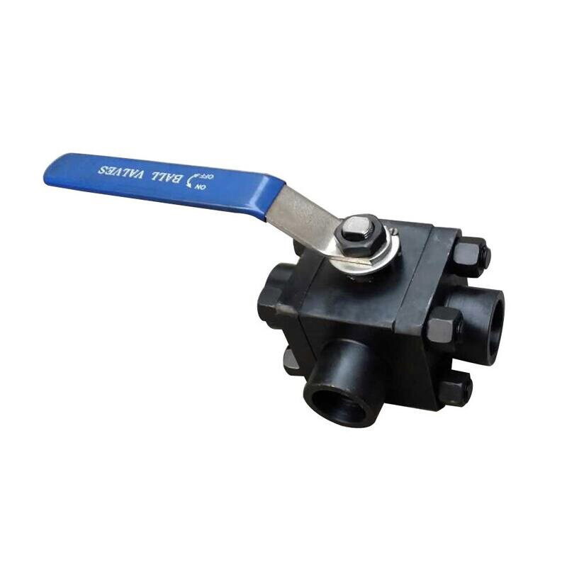
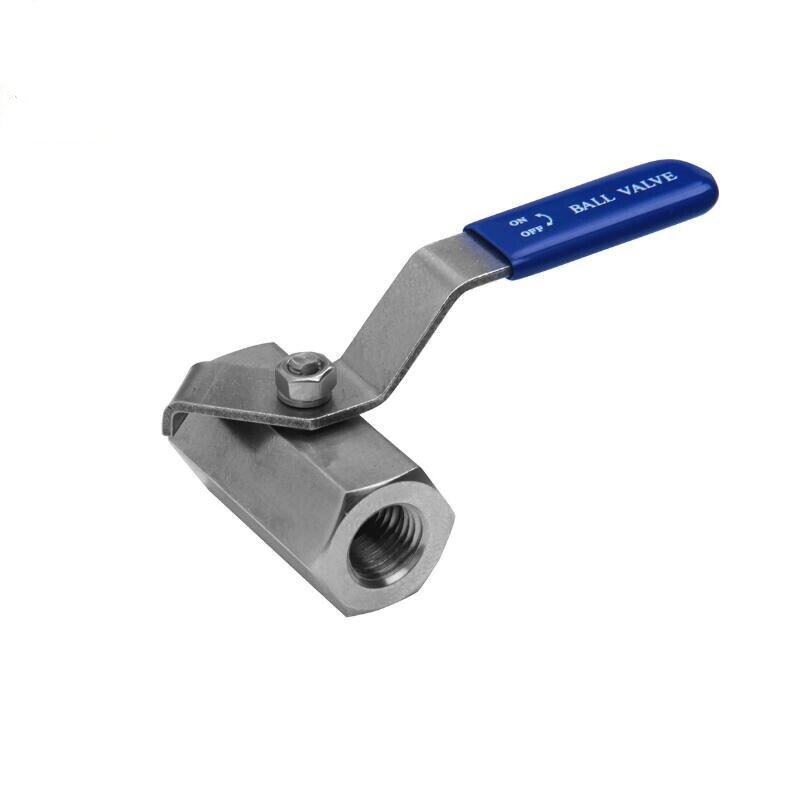
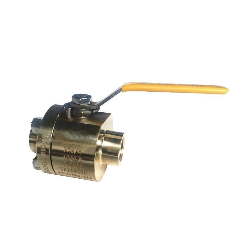
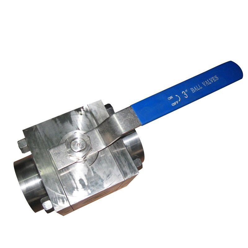
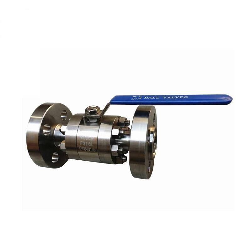
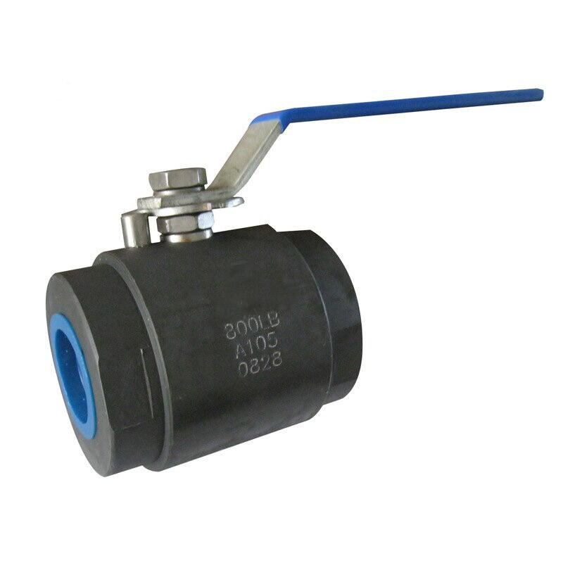
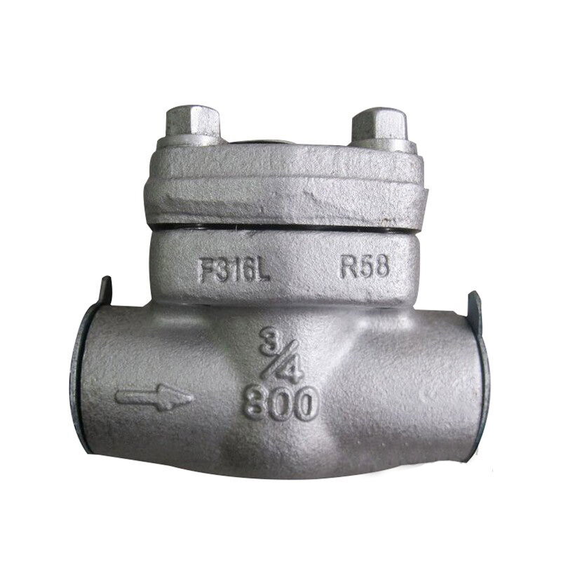
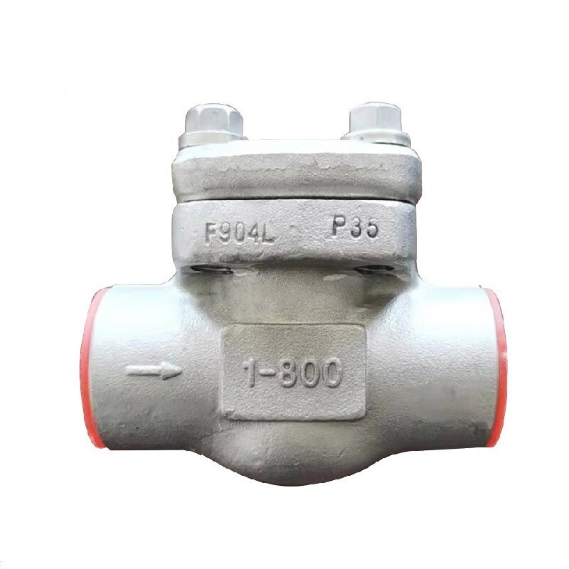
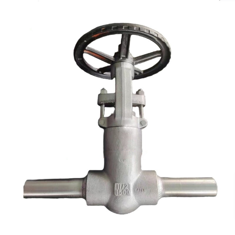
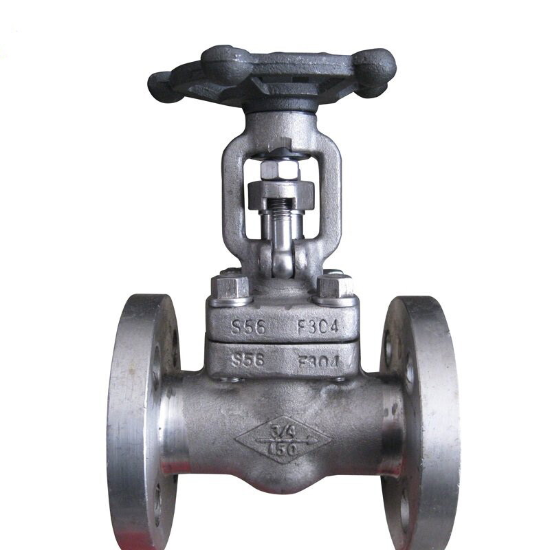
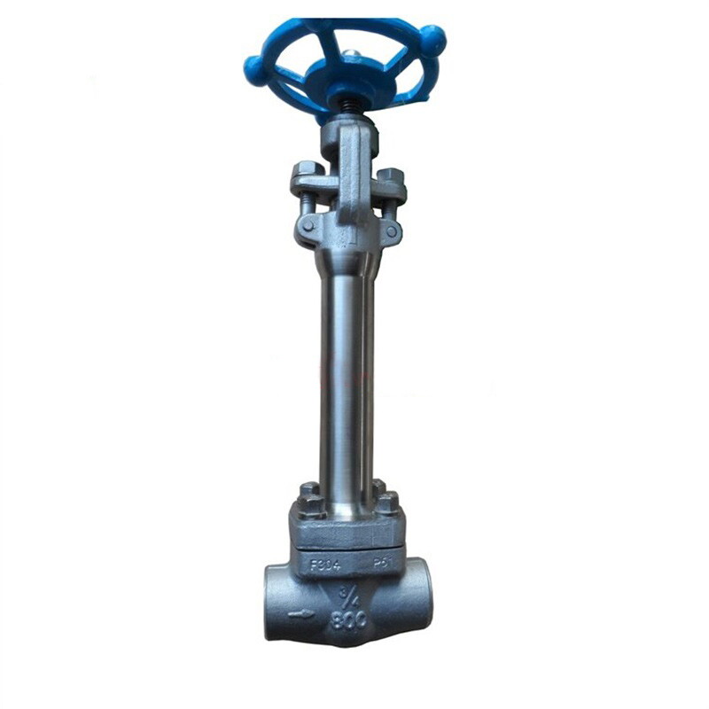
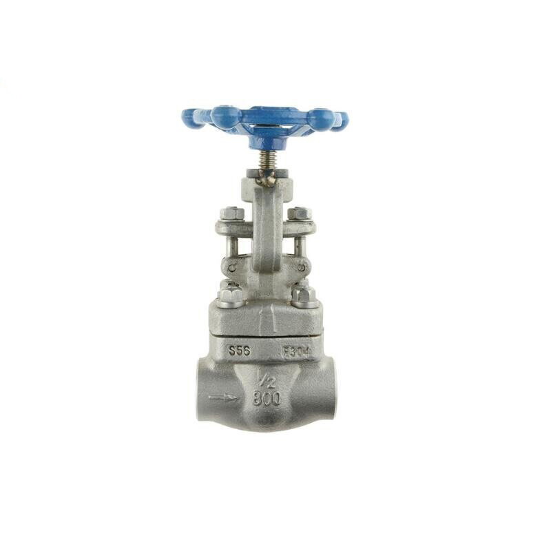
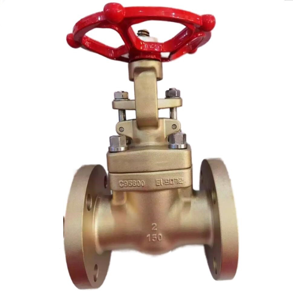
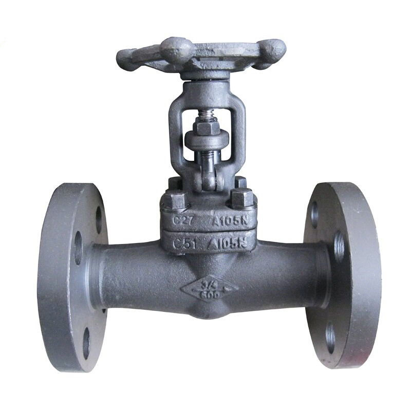
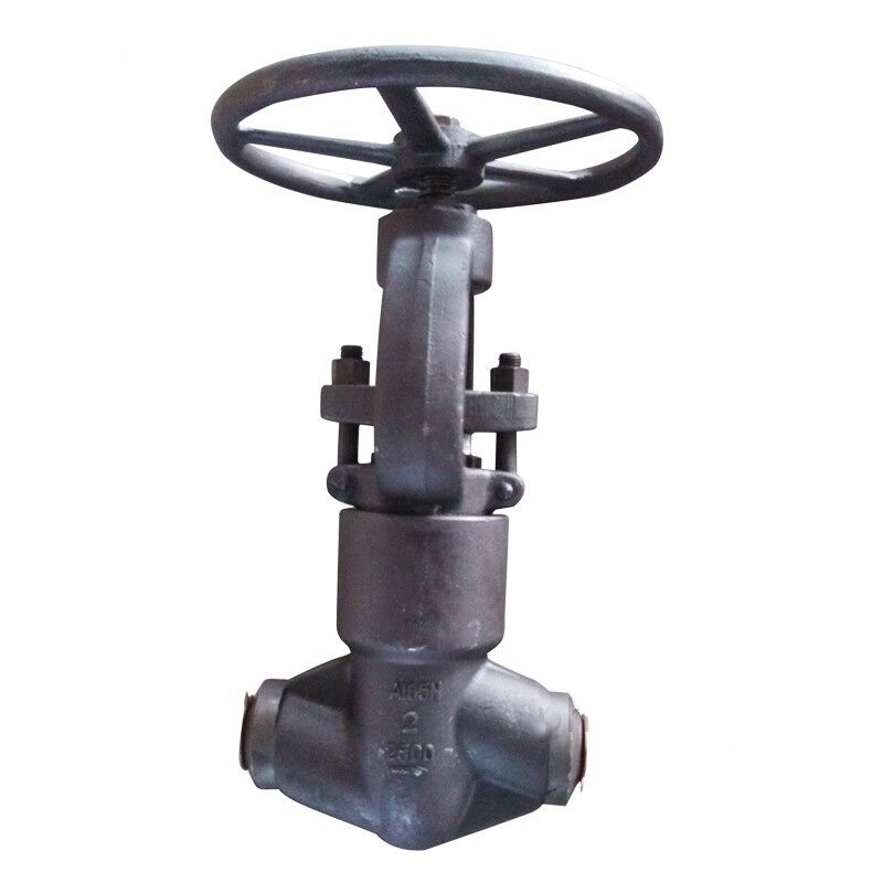
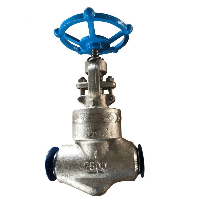
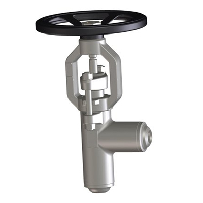
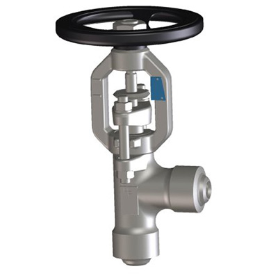
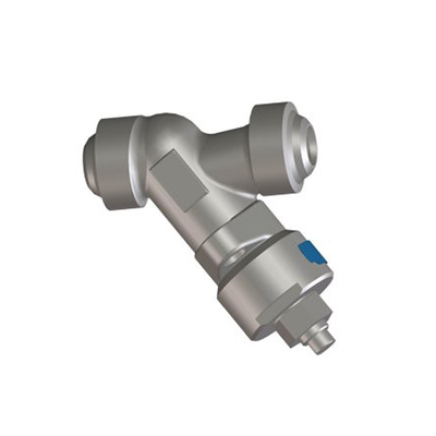
Forged Steel Valve
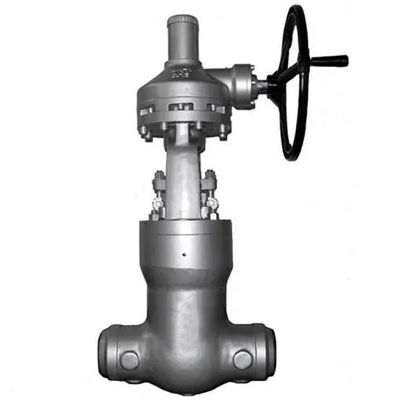
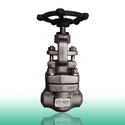
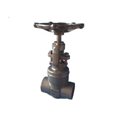
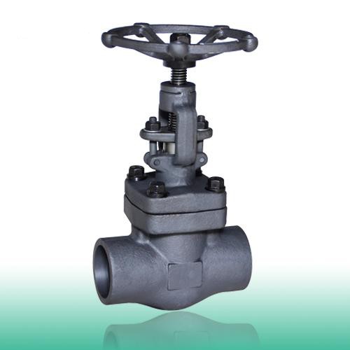
Compared with cast steel valves, forged valves show the advantages of more uniform structures, greater durability, closer dimensional tolerances, etc.
Material
Carbon steel, stainless steel, alloy steel, exotic alloy
A105, LF2, F5, F9, F91, F11, F22, F304, F304L, F316, F316L, F321, F347, Alloy 20
※Other materials are available to be customized. Please contact us for more details.
Standard
ASME B16.34, API 602, ISO 15761, API 6D, API 598, BS 5352
Type
Forged globe valve, forged gate valve, forged check valve, forged ball valve
Working Temperature
Cryogenic valve, high-temperature valve
Connection
Socket Weld, Butt Weld, NPT, Flanged
Major structures of forged steel ball valve: 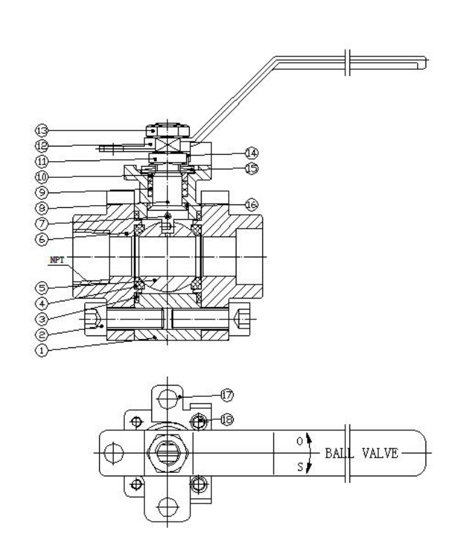
1. BODY. The body is forged steel and designed to the basic dimensional requirements of the applicable specifications such as API 6D. The body is available in both the full or standard port design.
2. BONNET BOLTING. The bonnet bolting is manufactured of alloy steel in accordance with the requirements of the applicable specifications such as API 602 and ASME B16.34.
3. GASKET. The bolted bonnet joint design valve uses a contained, controlled compression, spiral wound type gasket.
4. SEAT RINGS. The seat rings are steel and makeup part of the valve trim. They are pressed into the valve body and wedged into place, forming a seal with the body. The seating surfaces are ground and lapped.
5. BALL. The ball, which is solid design, is forged or investment cast steel and is part of the valve trim. The seating surfaces are ground and lapped.
6.BONNET. The bonnet is forged steel,which has dimensions per the applicable specifications such as API 6D.
7. SPRING. The spring with The steel/stainless steel material. It can put Seal onto the ball to seal up.
8. STEM. The stem is forged steel and part of the valve trim. It contains an integral back seat shoulder, which mates with the integral backseat of the bonnet. The stem is designed to the basic dimensional requirements of the applicable specifications such as API 602.
9. GLAND PACKING. The packing Install into the stuffing box of the bonnet , followed by pressing the valve stem bonded to form a seal.
10. GLAND AND FLANGE. The gland, gland flange assembly utilizes a separate, two piece design. This self aligning design allows the flange to be unevenly tightened while the gland maintains its parallel alignment with the stem and stuffing box.
11. GLAND BOLTS AND NUTS. The steel/stainless steel gland bolt and nut assembly is a stud eyebolt arrangement. This design allows complete removal from the valve when service is required. The use of industry standard thread full length studs and nuts also allows easy replacement should these items be lost or in need of replacement.
12.Lever. Handle install directly to the stem, urging to handle the handle is passed directly to the stem.
13. Lock nut . The steel/stainless steel nut, it is used to Fixed ball handle or lever .
14. Lock washer. The lock washer normally is stainless steel or other similar material . is widely used in bearings, lock nut, washer, its good durability.
15. Belleville spring. The shape of belleville spring is conical dish the different from traditional spring is that it has its special role in the function of the main characteristics, load, short stroke and small space required, the combination of easy to use, easy to maintain facelift, economic security high small for space, a large load of heavy precision machinery between 10% -75% of its compression stroke range of optimum operation at its maximum compression stroke.
16.Back seat. Back seat sealing force increases with increasing media pressure, strengthen the reliability of the seal packing.
17. Lock device. The lock device matched on the lever.The opening of the valve itself comes with locking means available to limit, to avoid accidents caused by open and non-normal use, it can be used to control a variety of important and dangerous gases and liquids, play a security role.
18. Bolt. The steel/stainless steel gland bolt and nut assembly is a stud eyebolt arrangement. This design allows complete removal from the valve when service is required. The use of industry standard thread full length studs and nuts also allows easy replacement should these items be lost or in need of replacement.
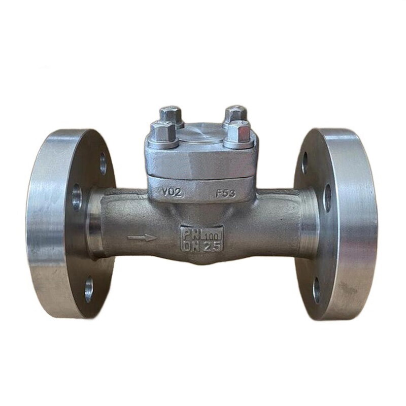
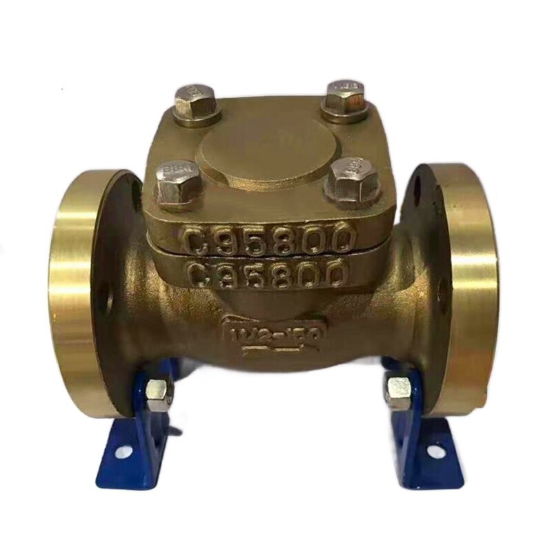
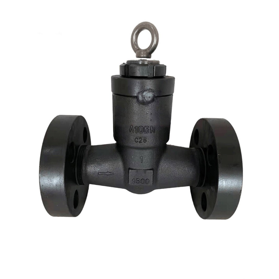
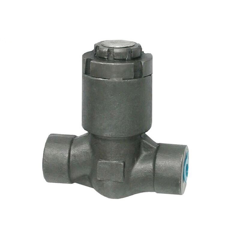
Major structures of forged steel check valve: 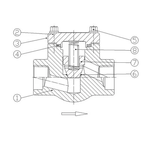
1. BODY. The body is forged steel and designed to the basic dimensional requirements of the applicable specifications such as API 602 and ASME B16.34. The body is available in both the full or standard port design. It is also available in either T-Pattern or Y-Pattern configurations.
2. COVER. The cover is forged steel and designed to the basic dimensional requirements of the applicable specifications such as API 602 and ASME B16.34.
3. BODY-COVER JOINT. Two different cover joint designs are available. These are either the bolted cover or the threaded and seal welded type.
4. GASKET. The bolted cover joint design valve uses a contained, controlled compression, spiral wound type gasket
5. COVER BOLTING. The cover bolting is manufactured of alloy steel in accordance with the requirements of the applicable specifica-tions such as API 602 and ASME B16.34.
6. SEAT. The body seat for the piston and ball check valves is an integral weld overlay and is part of the valve trim. The swing check valve is supplied with a separate seat ring which is pressed into the valve body and wedged into place, forming a seal with the body.
7. PISTON, BALL OR DISC. The piston, ball or disc is forged steel and is part of the valve trim. The seating surface of the piston and ball check is of the tapered or plug type design. The seating surface of the swing check is of the flat seat design.
8. SPRING. The spring is optional and supplied only upon request.
Major structures of forged steel gate valve: 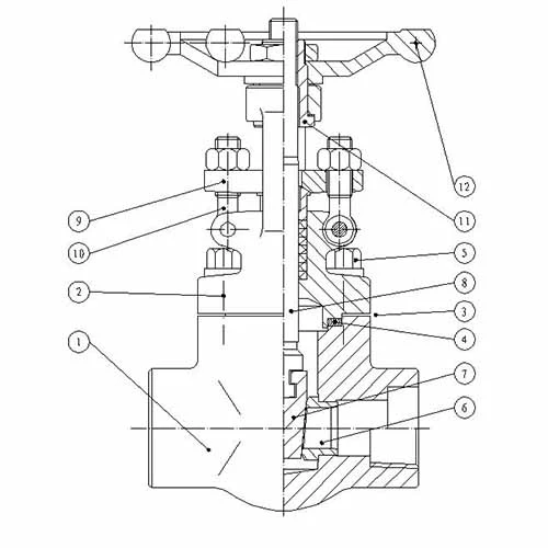
1. BODY. The body is forged steel and designed to the basic dimensional requirements of the applicable specifications such as API 602 and ASME B16.34. The body is available in both the full or standard port design.
2. BONNET. The bonnet is forged steel, has an integral backseat and incorporates the stuffing box, which has dimensions per the applicable specifications such as API 602.
3. BODY-BONNET JOINT. Two different bonnet joint designs are available. These are either the bolted bonnet or the threaded and seal welded type.
4. GASKET. The bolted bonnet joint design valve uses a contained, controlled compression, spiral wound type gasket.
5. BONNET BOLTING. The bonnet bolting is manufactured of alloy steel in accordance with the requirements of the applicable specifications such as API 602 and ASME B16.34.
6. SEAT RINGS. The seat rings are steel and makeup part of the valve trim. They are pressed into the valve body and wedged into place, forming a seal with the body. The seating surfaces are ground and lapped.
7. WEDGE. The wedge, which is solid design, is forged or investment cast steel and is part of the valve trim. The seating surfaces are ground and lapped
8. STEM. The stem is forged steel and part of the valve trim. It contains an integral back seat shoulder, which mates with the integral backseat of the bonnet. The stem is designed to the basic dimensional requirements of the applicable specifications such as API 602.
9. GLAND AND FLANGE. The gland, gland flange assembly utilizes a separate, two-piece design. This self aligning design allows the flange to be unevenly tightened while the gland maintains its parallel alignment with the stem and stuffing box.
10. GLAND BOLTS AND NUTS. The steel/stainless steel gland bolt and nut assembly is a stud, eyebolt arrangement. This design allows complete removal from the valve when service is required. The use of industry standard thread full length studs and nuts also allows easy replacement should these items be lost or in need of replacement.
11. YOKE SLEEVE. The yoke sleeve is of forged stainless steel material having a high melting point and is resistant to wear and corrosion.
12. HANDWHEEL. The handwheel is forged carbon steel of an open spoke design. This robust construction along with appropriate sizing allows for ease of operation.
Major structures of forged steel globe valve: 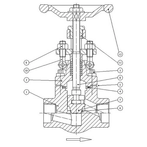
1. BODY. The body is forged steel and designed to the basic dimensional requirements of the applicable specifications such as API 602 and ASME B16.34. The body is available in both the full or standard port design. It is also available in either T-pattern or Y-pattern configuration.
2. BONNET. The bonnet is forged steel, has an integral backseat and incorporates the stuffing box, which has dimensions per the applicable specifications such as API 602.
3. BODY-BONNET JOINT. Two different bonnet joint designs are available. These are either the bolted bonnet or the threaded and seal welded type.
4. GASKET. The bolted bonnet joint design valve uses a contained, controlled compression, spiral wound type gasket.
5. BONNET BOLTING. The bonnet bolting is manufactured of alloy steel in accordance with the requirements of the applicable specifications such as API 602 and ASME B16.34.
6. SEAT. The body seat is an integral weld overlay and is part of the valve trim.
7. DISC. The disc is forged steel and is part of the valve trim. The disc seating surface is of the tapered or plugs type design. The disc is attached to the stem using a loose or swivel disc arrangement.
8. STEM. The stem is forged steel and part of the valve trim. It contains an integral back seat shoulder, which mates with the integral backseat of the bonnet. The stem is designed to the basic dimensional requirements of the applicable specifications such as API 602.
9. GLAND AND FLANGE. The gland, gland flange assembly utilizes a separate, two piece design. This self aligning design allows the flange to be unevenly tightened while the gland maintains its parallel alignment with the stem and stuffing box.
10. GLAND BOLTS AND NUTS. The steel/stainless steel gland bolt and nut assembly is a stud, eyebolt arrangement. This design allows complete removal from the valve when service is required. The use of industry standard thread full length studs and nuts also allows easy replacement should these items be lost or in need of replacement.
11. YOKE SLEEVE. The yoke sleeve is of forged stainless steel material having a high melting point and is resistant to wear and corrosion.
12. HANDWHEEL. The handwheel is forged carbon steel of an open spoke design. This robust construction along with appropriate sizing allows for ease of operation.
Products
About Us
Best Categories
Useful Links
