The Multi-Directional Die Forging Process of High-Pressure Plug Valves
The Multi-Directional Die Forging Process of High-Pressure Plug Valves
Nov 14, 2024
On this page
High-pressure pipes play an important role in oil industry equipment and are widely used in oilfield drilling, cementing, logging, and fracturing operations. They are also used in oil testing operations, continuous tubing operations, sand control operations, and offshore platforms. As the difficulty of fracturing operations increases, the pressure level of the manifold continues to rise, with a pressure load capacity of 105MPa becoming more common. The plug valve controls the circulation and shutoff of the medium through the rotation of the plug and is an important high-pressure product in well site operations. Figure 1 shows common forged plug valves used in high-pressure pipes.
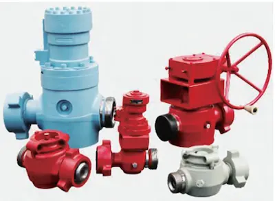
Figure 1 High-pressure plug valve

Figure 1 High-pressure plug valve
Forging and Die Design
The product specification is for a 2-inch plug valve with a pressure level of 105MPa. The material is ultra-high-strength steel 42CMoA, the part weighs 30 kg, and the overall valve body has four-way interconnecting cavities and a hexagonal structure on both horizontal sides. The part diagram is shown in Figure 2. Based on the part structure, the forging design is shown in Figure 3. No machining allowance is provided on the non-machined surface of the forging. A 60 mm deep blind hole is designed in the direction of the valve core installation in the valve body. Due to the small horizontal aperture, the raw material cost is minimized, and a solid structure is used to increase the service life of the mold. The forging is formed by a multi-directional die forging process without flash burrs. The overall mass of the forging is 46 kg, and the material utilization rate is about 65%.
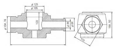
Figure 2 Parts drawing
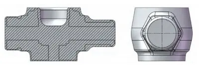
Figure 3 Forging drawing

Figure 2 Parts drawing

Figure 3 Forging drawing
Mold Design
Based on the forging structure design, the multi-directional die forging assembly structure shown in Figure 4 is established. To ensure fuller metal filling, only a horizontal punch is placed at the horizontal end of the forging to achieve metal extrusion. The mold consists of five parts: the upper die, lower die, upper punch, horizontal punch, and lower ejector.
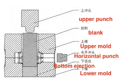
Figure 4 Die assembly structure

Figure 4 Die assembly structure
Finite Element Numerical Simulation
Geometric Model Establishment
Since the product structure is symmetrical from front to back, a 1/2 model is selected for the simulation calculation to reduce calculation time and improve accuracy. The finite element model is shown in Figure 5, and the model in "stI" format is imported into the DEFORM-3D pre-processing module.
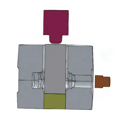
Figure 5 Establishing the finite element model

Figure 5 Establishing the finite element model
Setting Boundary Conditions
The forging is made from 42CrMoA, and the corresponding AISI-4140 is selected in the DEFORM-3D material library. The blank is a 150mm × 334mm round bar, and the blank temperature is set to 1200°C. The die is AISI-H13, and the die temperature is set to 200°C. The heat exchange coefficient between the blank and the die is 8kW/(m²•°C). The friction between the blank and the die follows the shear friction model, with a friction factor of 0.15, and the die movement speed is set to 25mm/s.
Simulation Process Flow Setting
For the multi-directional die forging process of 2-inch, 105MPa plug valve forgings, the production process is mainly divided into the following steps: heating the blank and placing it in the cavity, closing the upper die, upper punch extrusion, horizontal punch extrusion, upper punch return, horizontal punch return, and opening the upper die to eject the forging. The simulation analysis focuses only on the steps of upper die closing, upper punch extrusion, and horizontal punch extrusion to analyze the forging forming quality, forming load, and forging temperature field.
Simulation Result Analysis
Figure 6 shows a simulation diagram of the multi-directional die forging process for forming a 2-inch, 105MPa plug valve body. The heated billet is placed in the lower mold cavity, and the upper die moves downward to complete the die closing step, as shown in Figure 6 (b). The upper punch then moves downward to upset the billet, and its action achieves the upsetting and blind hole extrusion of the billet. The metal billet flows downward into the horizontal cavities on both sides of the die cavity. First, the horizontal rough end of the die cavity is filled with metal, as shown in Figures 6 (c) and 6 (d). The upper punch is then extruded to the set displacement, and the horizontal punch is extruded inward to complete the upsetting of the horizontal end of the forging, as shown in Figure 6 (e). The formed forging is obtained, as shown in Figure 6 (f). The basic process parameters of the press are determined based on the simulation results. The upper punch extrusion process relies on displacement control, while the horizontal end forming of the forging depends on horizontal load control of the press. As shown in Figure 7, a 1/2 model is selected for analysis. At this point, the horizontal end face of the forging is just filled, and the final horizontal forming load simulation value is 4.8 MN.
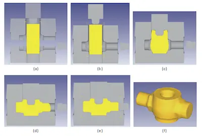
Figure 6 Forging forming process flow chart
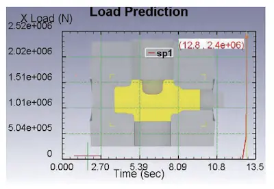
Figure 7 Horizontal punch load

Figure 6 Forging forming process flow chart

Figure 7 Horizontal punch load
Simulation Results of the Temperature Field
Upon reviewing the simulation results of the forging temperature field, it was found that the overall temperature distribution is uniform, and the forging temperature in the contact area with the die cavity surface and the upper punch face is relatively low. However, when the horizontal end begins forging, the metal in this area has already been forged and no longer flows, so its impact on forging is relatively small. After the horizontal end is formed, the temperature of the end-face metal remains high, around 1100°C, which meets the forging temperature control range.
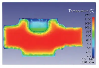
Figure 8 Forging temperature field distribution

Figure 8 Forging temperature field distribution
Test Preparation
The multi-directional die forging test for the 2-inch 105MPa plug valve forgings was conducted on China's 40MN multi-directional die forging production line and its supporting equipment. The process flow is as follows: blanking, billet heating, die preparation, oxide scale removal, multi-directional die forging, forging shot blasting, and non-destructive testing. Considering that the test process uses a chamber furnace for heating, oxidation and burning of the billet occur during the process, with a burning rate of approximately 3%. The designed forging mass is 46 kg, so the blanking mass is set to 47.4 kg. The material used is 42CrMoA, with a 150 mm rolled round bar, and a band saw is used for cutting. The hot test process uses a high-temperature chamber furnace for heating. The furnace temperature is set to 1200°C according to relevant literature standards, and the mold preheating temperature is above 200°C. The lubricant is diluted and blended with water-based graphite in a 1:3 ratio for mold lubrication and cooling.
Test Process
Before the test, the mold is preheated to the set temperature range, and the heated billet in the box-type resistance furnace is taken out and transferred to the high-pressure water descaling machine for surface oxide removal, as shown in Figure 9(b). The billet, after oxide removal, is clamped by the loading robot and placed in the mold cavity, and the press forges it, as shown in Figures 9(c) and 9(d). After forging, the mold is opened, the punch returns, and the lower part is ejected, as shown in Figure 9(e). The robot then takes out the forging, as shown in Figure 9(f), completing the forging process.
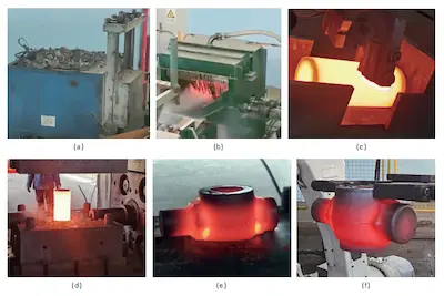
Figure 9 Mass production of forgings
Following the forging process flow, the forging is trial-produced and shot blasted after cooling. The appearance quality of the forging is good, the fillet is full, and there is no flash, burr, or folding on the surface. The forging is subjected to ultrasonic and magnetic particle inspections, and the results show that the forging has no defects, such as internal cracks or surface scars. The test sample in Figure 10(a) is consistent with the simulated forging in Figure 10(b).
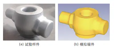
Figure 10 Appearance quality of forgings

Figure 9 Mass production of forgings
Following the forging process flow, the forging is trial-produced and shot blasted after cooling. The appearance quality of the forging is good, the fillet is full, and there is no flash, burr, or folding on the surface. The forging is subjected to ultrasonic and magnetic particle inspections, and the results show that the forging has no defects, such as internal cracks or surface scars. The test sample in Figure 10(a) is consistent with the simulated forging in Figure 10(b).

Figure 10 Appearance quality of forgings
Forming Load Analysis
According to the previous forming process requirements, the forming process parameters of the upper punch of the press are displacement-controlled, and the process parameters of the horizontal punch are load-pressure controlled. During the trial production process, the extrusion load applied by the horizontal punch was continuously adjusted. Finally, it was determined that when the horizontal extrusion pressure reached 4.1MN, the plug valve forging with full quality could still be formed. The simulation data and test data are shown in Table 1. The test value was 0.7MN smaller than the simulation value.
Table 1 Comparison of forming loads
Table 1 Comparison of forming loads
| Simulation value | Real value | Difference |
| 4.8MN | 4.1MN | 0.7MN |
Batch Production
Based on the results of the hot test data, the forming process parameters of the forging press were adjusted, and the pressing load of the horizontal punch was modified to 4.1MN. Through production verification, the forging quality is good, the production process is smooth and efficient, and the product qualification rate reaches 100%. The batch-produced forgings are shown in Figure 11.
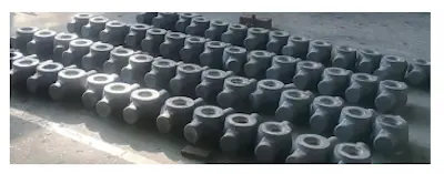
Figure 11 Mass produced forgings

Figure 11 Mass produced forgings
Conclusion
This paper utilizes multi-directional die forging technology to conduct numerical simulation analysis of high-pressure manifold plug valve forgings and completes the test and batch production on the 40MN multi-directional die forging production line. The results show that plug valves for this type of petroleum high-pressure pipes can be successfully forged using multi-directional die forging equipment. The multi-directional die forgings have small machining allowances, high material utilization, and good surface quality, which fully demonstrates the rationality and feasibility of this product's multi-directional die forging process.
Next: Modular Structure & Design of a Small-Diameter Forged Regulating Valve for LNG Systems
Previous: How to Master the Marketing of Valves?
News
About Us
Best Categories
Useful Links