Modular Structure & Design of a Small-Diameter Forged Regulating Valve for LNG Systems
Modular Structure & Design of a Small-Diameter Forged Regulating Valve for LNG Systems
Nov 27, 2024
On this page
Abstract: In the LNG industry, achieving a high adjustability ratio in a small-diameter globe regulating valve that must handle both large and micro flow rates is challenging. To address this challenge, a modular valve trim design was developed, combining structures for both large and small flow regulation after analyzing the technical requirements and design difficulties. This modular design builds on the existing structure of the large-flow regulating valve. By adding a small-flow component, the valve core can be interchanged to support ultra-small flow coefficients (Cv=0.17, 0.7) and large flow coefficients (Cv=11.7, 16) under -196°C operating conditions, without altering the original valve structure. This enhanced design not only simplifies product processing but also effectively reduces manufacturing costs.
1. Overview
Liquefied Natural Gas (LNG) is derived from natural gas extracted from gas fields. The natural gas is purified by removing acidic gases, dehydrating, extracting heavy hydrocarbons, and then compressing, expanding, and liquefying. The resulting LNG is a flammable and explosive liquid that requires storage at low to ultra-low temperatures, between -196°C and -39°C. LNG valves are primarily used in natural gas liquefaction plants, LNG transport systems, and LNG receiving stations. Regulating valves are a specialized type of valve used in LNG systems. These valves typically feature ultra-low temperature tolerance, adjustable flow control, zero leakage, and an extended bonnet design. This article focuses on the operational conditions and requirements of an international LNG project. It examines valve design for ultra-low temperature and variable flow control conditions, achieving product improvement and manufacturing efficiency through a modular structure.
2. Technical Requirements
Based on the design parameters of a specific LNG project, this valve features a nominal diameter of NPS 1.5, a nominal pressure of CLASS 600, a globe-style structure, and a flanged connection. It is a small-diameter, forged steel regulating valve for LNG systems. Special requirements include a one-piece die-forged valve body and bonnet, a fluid channel that complies with ASTMB16.34 standards, and two valve design options—Throttle and Needle—each with specific Cv values. Interchangeability between the two types must be ensured, and all components, except for the valve core, should be standardized. The flow coefficient must also meet the specifications for ultra-small flow rates (Cv = 0.17, 0.7) in Needle valves and high flow rates (Cv = 11.7, 16) in Throttle valves. The interchangeability and flow characteristics of each valve core are precisely calibrated based on equal percentage adjustments.
3. Analysis of Design Challenges
Based on technical requirements, the valve design presents several challenges:
(1) The valve body uses a single-piece forged flange design, with the channel size maintained at no less than 90% of the nominal diameter or as specified in the non-mandatory Appendix A of ASMEB16.34 (Figure 1).
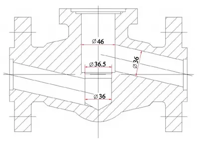
Figure 1 NPS1.5 forged steel valve body plan view
(2) The valve bonnet is manufactured as an integral die forging with an extended diameter and must not be welded. The inverted seal is positioned close to the bottom of the stuffing box to prevent abnormal pressure increases in the valve due to temperature fluctuations, adding to the processing complexity (Figure 2).
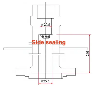
Figure 2 NPS1.5 forged steel valve bonnet plan view
(3) Designing a Needle Valve with an ultra-small Cv value for a full-diameter valve seat is highly challenging, requiring exceptional processing precision and nearly impossible to achieve in practice. For example, even disregarding the influence of valve body structure and machining tolerances, with a rated Cv of 0.7, the calculated flow area at 100% open is 15 mm². If the valve seat’s inner diameter is 36 mm, the gap between the valve seat and core must be controlled to 0.183 mm. Under equal percentage characteristics, the flow area at 10% opening is 0.77 mm², requiring the gap between the valve seat and core to be controlled to just 0.007 mm. Achieving this level of precision is extremely difficult with standard machining methods.
(4) When Cv = 11.7, the throttle valve must utilize small-hole valve cores with an equal percentage characteristic, as required. In theory, if only the valve core structure with Cv = 11.7 is considered, it can be designed. However, due to the limited cavity area of the compact valve body and the restricted stroke, Cv = 11.7 is nearly at its maximum, which significantly impacts the design and shape of the valve core. As shown in Figure 1, the space with an inner diameter of 46 mm is clearly insufficient.
(5) Under these conditions, designing internal components for ultra-small flow Cv (needle valve) and large flow Cv (throttle valve) requires a larger adjustable ratio internal component. However, designing globe regulating valves is extremely challenging. The control accuracy is also suboptimal, and the results do not meet the control requirements for various operating conditions. Therefore, a reliable solution must be considered to address this challenging issue.
(5) Under these conditions, designing internal components for ultra-small flow Cv (needle valve) and large flow Cv (throttle valve) requires a larger adjustable ratio internal component. However, designing globe regulating valves is extremely challenging. The control accuracy is also suboptimal, and the results do not meet the control requirements for various operating conditions. Therefore, a reliable solution must be considered to address this challenging issue.
4. Modular Design of Different CV Internal Parts
To address the issues outlined above, a modular design approach is used, and the basic valve parameters are first determined based on 90% of the nominal diameter requirement. The inner diameter of the channel and valve seat is 36 mm. The valve body and bonnet are integrally forged as compact globe valves, as shown in Figures 3 and 4.
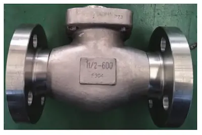
Figure 3 NPS1.5 forged steel valve body
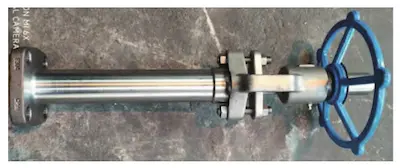
Figure 4 NPS1.5 forged steel valve bonnet parts
First, design two structures with large flow Cv values of 16 and 11.7 (throttle valve). Through calculations and experience, it is evident that due to the limited flow capacity of the compact valve body (Cv = 27), when the flow coefficient is Cv=16, a small-hole valve core is used. However, it is not possible to arrange additional small holes in the circumferential area of the valve core. As a result, it must be designed as a single-seat plunger structure, as shown in Figures 5 and 6. Calculations show that Cv=11.7 can be designed as a small-hole valve core under a limited stroke and can meet the requirements for equal percentage adjustment characteristics, as shown in Figures 7 and 8.
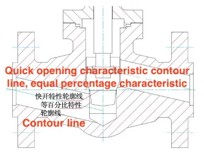
Figure 5 Single-seat plunger structure

Figure 6 Single-seat plunger valve core

Figure 7 The regulating valve core structure of the valve hole type valve core
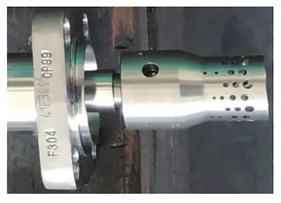
Figure 8 Small hole valve core
Next, design the small-flow Cv structure for the needle valve. When the inner diameter of the original valve seat remains at 36 mm, the only way to achieve a needle valve with Cv = 0.17 and 0.7 is to reduce the valve seat’s inner diameter. Therefore, a valve seat sealing sleeve structure, based on the throttle valve design, is proposed. This structure relies on the valve bonnet seal to apply pressure between the valve seat sealing sleeve (Figure 9) and the throttle valve seat, forming the first seal and reducing the valve seat’s inner diameter from 36 mm to 6-8 mm. Considering manufacturing process requirements and calculations, the valve core structure is designed in three types: an equal percentage cylindrical plug needle structure (Figure 10), an open V-groove plunger structure (Figure 11), and a cylindrical double-sided flat structure (Figure 12). Taking Figure 10 as an example, calculate the gap between the valve seat and valve core at the fully open position with a rated Cv of 0.7 to be 1.002 mm. Calculate the gap between the valve seat and valve core at the 10% opening position to be 0.042 mm. Clearly, after reducing the valve seat, the processing of the valve core becomes easier. However, the accuracy requirements for both the valve seat and core are higher, particularly for the Cv = 0.17 design. This is due to the throttling ring area being converted into unit length during processing. If the valve core is designed as an open V-groove plunger or a cylindrical double-sided flat structure, the equivalent ring area is converted into one or two semicircular areas, thereby reducing processing accuracy requirements. Comparing the processing technologies of the two structures, achieving an equal percentage adjustable ratio (R = 30) for the V-groove plunger structure is relatively difficult, while milling the cylindrical surface of the cylindrical double-sided flat structure is easier. Therefore, the cylindrical double-sided flat structure was ultimately adopted (Figure 12). This not only solves the processing problem but also easily achieves ultra-small Cv control. At this stage, based on the large flow rate of the original throttle valve, replacing the valve seat sealing sleeve structure and matching two parts with different Cv valve cores enables ultra-small flow control and valve core interchangeability, while also meeting the needs of the LNG process system.
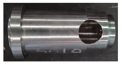
Figure 9 Valve seat sealing sleeve
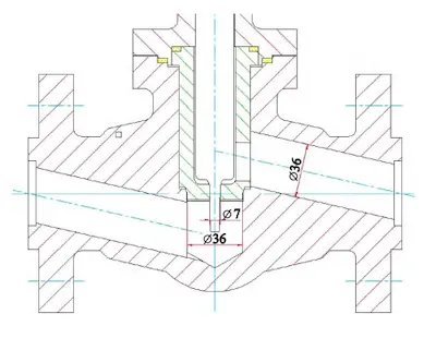
Figure 10 Cylindrical plug needle type structure
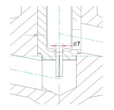
Figure 11 V-groove plunger structure
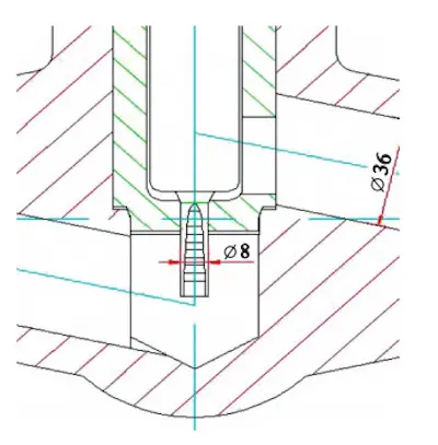
Figure 12 Cylindrical double-sided flat structure

Figure 13 Cylindrical double-sided flat valve core and sleeve

Figure 3 NPS1.5 forged steel valve body

Figure 4 NPS1.5 forged steel valve bonnet parts
First, design two structures with large flow Cv values of 16 and 11.7 (throttle valve). Through calculations and experience, it is evident that due to the limited flow capacity of the compact valve body (Cv = 27), when the flow coefficient is Cv=16, a small-hole valve core is used. However, it is not possible to arrange additional small holes in the circumferential area of the valve core. As a result, it must be designed as a single-seat plunger structure, as shown in Figures 5 and 6. Calculations show that Cv=11.7 can be designed as a small-hole valve core under a limited stroke and can meet the requirements for equal percentage adjustment characteristics, as shown in Figures 7 and 8.

Figure 5 Single-seat plunger structure

Figure 6 Single-seat plunger valve core

Figure 7 The regulating valve core structure of the valve hole type valve core

Figure 8 Small hole valve core
Next, design the small-flow Cv structure for the needle valve. When the inner diameter of the original valve seat remains at 36 mm, the only way to achieve a needle valve with Cv = 0.17 and 0.7 is to reduce the valve seat’s inner diameter. Therefore, a valve seat sealing sleeve structure, based on the throttle valve design, is proposed. This structure relies on the valve bonnet seal to apply pressure between the valve seat sealing sleeve (Figure 9) and the throttle valve seat, forming the first seal and reducing the valve seat’s inner diameter from 36 mm to 6-8 mm. Considering manufacturing process requirements and calculations, the valve core structure is designed in three types: an equal percentage cylindrical plug needle structure (Figure 10), an open V-groove plunger structure (Figure 11), and a cylindrical double-sided flat structure (Figure 12). Taking Figure 10 as an example, calculate the gap between the valve seat and valve core at the fully open position with a rated Cv of 0.7 to be 1.002 mm. Calculate the gap between the valve seat and valve core at the 10% opening position to be 0.042 mm. Clearly, after reducing the valve seat, the processing of the valve core becomes easier. However, the accuracy requirements for both the valve seat and core are higher, particularly for the Cv = 0.17 design. This is due to the throttling ring area being converted into unit length during processing. If the valve core is designed as an open V-groove plunger or a cylindrical double-sided flat structure, the equivalent ring area is converted into one or two semicircular areas, thereby reducing processing accuracy requirements. Comparing the processing technologies of the two structures, achieving an equal percentage adjustable ratio (R = 30) for the V-groove plunger structure is relatively difficult, while milling the cylindrical surface of the cylindrical double-sided flat structure is easier. Therefore, the cylindrical double-sided flat structure was ultimately adopted (Figure 12). This not only solves the processing problem but also easily achieves ultra-small Cv control. At this stage, based on the large flow rate of the original throttle valve, replacing the valve seat sealing sleeve structure and matching two parts with different Cv valve cores enables ultra-small flow control and valve core interchangeability, while also meeting the needs of the LNG process system.

Figure 9 Valve seat sealing sleeve

Figure 10 Cylindrical plug needle type structure

Figure 11 V-groove plunger structure

Figure 12 Cylindrical double-sided flat structure

Figure 13 Cylindrical double-sided flat valve core and sleeve
5. Conclusion
By improving the modular design of the LNG small-diameter forged steel regulating valve, a combination of large-flow and small-flow modular valve trim structures is used. This combination requires no modifications to the original valve structure and meets the shutdown requirement at -196°C. Under ultra-small flow conditions (Cv = 0.17 and 0.7) and large flow conditions (Cv = 11.7 and 16), the internal parts of each valve core are interchangeable. This modular design improvement not only reduces the product's processing difficulty but also effectively controls manufacturing costs.
Previous: How to Master the Marketing of Valves?
News
About Us
Best Categories
Useful Links